|
Archicad 28 C++ API
|
|
Archicad 28 C++ API
|
The required format of UserControl items in the .grc files always caused a headache. In this document, we'll explain the meaning of the different numbers behind the UserControl definition. Let's see them type by type. The examples were mostly taken from DG_Test, which is part of the development kit.
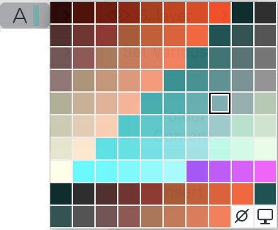
This control is a collection of special controls; it encapsulates controls which are very different in appearance, but not in functionality. Basically this control consists of a button, which pops up a palette when clicked. The content of the button is updated as the user moves the mouse above the palette.
Examples: material, pen, layer palette pop-up.

The generic format of this control is:
UserControl 87 82 33 19 257 0x0001 0x1100 0 /* Line Pen Setting */
Let's see the 'numbers' one by one:
| Item | Description | Example |
|---|---|---|
UserControl | the type of the dialog item | |
87 82 33 19 | the item's rectangle (top, left, width, height) | |
257 | the type of the user control | |
0x0001 | defines the subtype of the user control (see the constants starting with T257_ in UCDefs.h) Note: 0x0001 is T257_PEN, so this is a pen control | |
0x1100 | the upper byte modifies the appearance of the user control (see the constants starting with CS257_ in UCDefs.h) Note: not all the flags are valid for all types of controls the lower byte is always 00 | 0x11 is CS257_HEADER | CS257_SMALLFONT, so the pop-up palette will have a header, and the menu items and the header will use the small application font. |
0 | used in textual pop-ups only T257_TEXT and T257_MENU; it contains the id of the ‘'STR#’` resource containing the menu items Note: due to a bug in the dialog manager, this cannot be used at the moment |
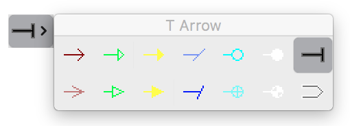
This control is an icon-based pop-up control. The icons coming from the specified resource appear on the pop-up palette.
Example: suspend groups selector on the control box.

The generic format of this control is:
UserControl 12 8 66 22 258 2 14 0 1 32520
Let's see the 'numbers' one by one:
| Item | Description |
|---|---|
UserControl | the type of the dialog item |
12 8 66 22 | the item's rectangle (top, left, width, height) |
258 | the type of the user control |
2 | specifies the number of rows you would like to see the icons |
14 | tells the total number of icons |
0 | always |
1 | modifies the appearance of the user control (combination of the constants starting with CS258_ in UCDefs.h) |
1 | is CS258_HEADER ⇒ the pop-up palette will have a header |
2 | is CS258_MOUSEPOSOPEN ⇒ the pop-up palette will appear relative to the mouse position, (as opposed to the control's rectangle) |
4 | is CS258_SIMPLEFRAME ⇒ the pop-up palette will have a simpler frame (Windows only) |
32510 | id of the icon resource; contains all the icons. This icon is cut into pieces to create the individual icons. This also servers as the resource ID of the title strings, if the popup palette has a header (CS258_HEADER). |
This control is an icon-based control. The icons coming from the specified resource are layed out flat.
Example: type selector in the library browser.

The generic format of this control is:
UserControl 12 8 30 28 259 1 3 0 0 32510
Let's see the 'numbers' one by one:
| Item | Description |
|---|---|
UserControl | the type of the dialog item |
12 8 30 28 | the item's rectangle (top, left, width, height) |
259 | the type of the user control |
1 | specifies the number of rows you would like to see the icons |
3 | tells the total number of icons |
0 | always |
0 | always |
32510 | id of the icon resource; contains all the icons |
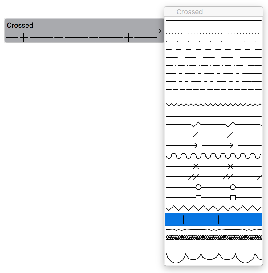
This control is the line type pop-up control. The content of the button is updated as the user moves the mouse above the palette. The specialty of this control is that it calls back to the server application to draw the line type into the control.
Example: any line type pop-up.

The generic format of this control is:
UserControl 42 0 260 40 261 0x0100 /* Line type for Line Tool */
Let's see the 'numbers' one by one:
| Item | Description | Example |
|---|---|---|
UserControl | the type of the dialog item | |
42 0 260 40 | the item's rectangle (top, left, width, height) | |
261 | the type of the user control | |
0x0100 | the upper byte modifies the appearance of the user control (see the constants starting with CS261_ in UCDefs.h) the lower byte is always 00 | 0x01 is CS261_HEADER, so the pop-up palette will have a header. |
I receive this error message: "This add-on cannot be validated. Please contact the distributor." What is the problem?
Several problems may lead to this message:


RegisterInterface () function.parentUnID field of the API_LibPart structure this way: ACAPI_LibraryPart_GetBuiltInLibpartUnId (132, libPart.parentUnID); // 132 is the 'FILE' resource IDplaceable, and clear the template field of the API_LibPart structure.How do I create an associative dimension in Archicad?
An example from the Automatic Dimensioning add-on shows how you can convert the old neig IDs to the new bool fields in API_Base :
_(Win only) My add-on runs perfectly on my development machine, but when I install it on a demo machine it refuses to load._
This usually happens from one of the following reasons:
Can I compile a GDL add-on, which uses the services of the General API DevKit?
No. GDL add-ons use their own API environment, and that mixes quite badly with the General API running environment.
How can I catch notifications immediately?
Return APIAddon_Preload from your CheckEnvironment () function. This will ensure that your Initialize () function will be called immediately after the call to Registerface (), without requiring the user to perform any action. You can then safely install the notification callback function(s) from Initialize ().
'GICN' 32501 "General Settings" {
0  128  128
}
The '0 128 128' is the R/G/B color (respectively) of the transparent area in the icon; each component is in the range 0-255. The reason why is doesn't compile with DevKit 6.1 is because some of the colors (black and white) should be in fixed places within the icon's color table: black should be the first color, and white should be the last. Note that the icons are converted to 32-bit depth, so you cannot use arbitrary big sizes.I'm creating a library part from my add-on, and I also put in a preview picture, but it doesn't appear.
From Archicad 8 you should add the MIME type of the preview picture as a C string (with the terminating 0) to the beginning of the data handle containing the preview picture. (e.g. "image/png\\0" for a PNG image)
Is there a default callback for the simple popup menu-like custom control?
No. You'll have to write your own callback to load the data from your resource file, and pass it to the user control with UC257SetData. You'll also have to call UC257SetType, and possibly UC257SetStyle. The DG_Test example now shows how you can work with these functions.
_(Win only) When I link my add-on, I receive the following warning: LINK : warning LNK4098: defaultlib "MSVCRT" conflicts with use of other libs; use /NODEFAULTLIB:library_
This only means that you are compiling the debug version of your add-on (thus linking to the debug version of the runtime DLLs), whereas the libraries shipped with the DevKit are release versions (which are linked to the release version of the runtime DLLs). This doesn't cause any problem.
How can I open a progress window when I have a long process running?
In several ways:
Do_ProgressWindow function in the DG_Test example. This is the recommended solution at the moment.I have a function which adjusts the additional parameter values of a placed object/window/door. It works fine in Archicad 7, but not in Archicad 8 or 9.
This problem usually occurs when you refer to the additional parameters by indices:
(*memo.params)[27].value.real = 7.25;
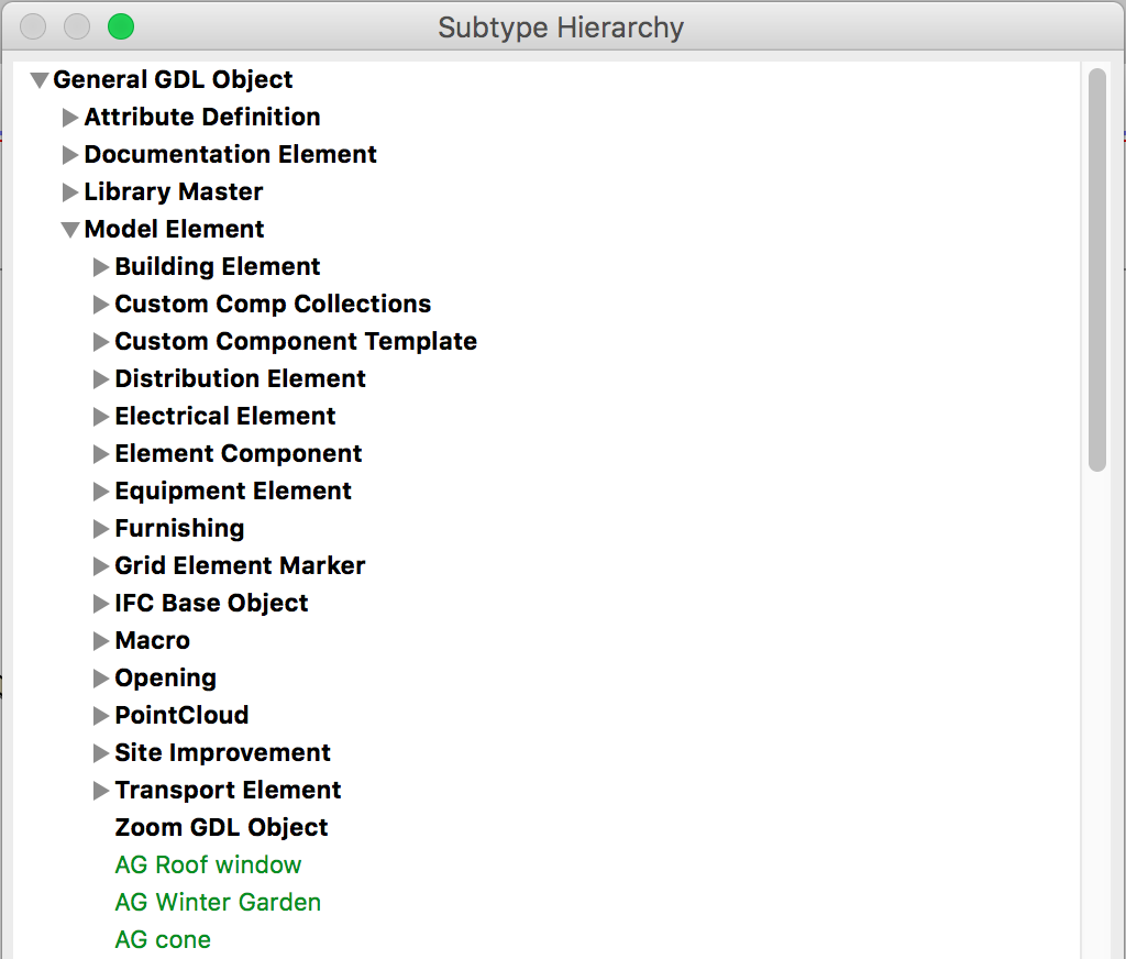
The problem is coming from the subtype hierarchy: an object/window/door in the hierarchy inherits the parameters of all of its ancestors. So, you should refer to a parameter by name instead of its index. This also means you'll have to look up the parameter by name before modify its value:
When I read 3D data for an element I don't get the correct 3D-vertex world-coordinates. They are local coordinates for that element. So how can I retrieve the correct vertex information in world coordinates of an element?
Each 3D body contains a transformation matrix (see API_BodyType), which should be applied to the coordinates of the vertices. This allows us to store a body which has several instances very compactly (i.e. store the vertices just once, and have a different transformation matrix for every instance).
How can I make the standard DXF/DWG add-on export elements into DWG file?
You can find a simple example at the description of the ACAPI_AddOnAddOnCommunication_Call function.